

1. Introduction
As concerns related to carbon emission and climate change grow gradually, there has been increased focus on the energy use in the buildings. The energy consumption in the building sector contributes up to 50% of global energy consumption in the developed countries (). The relative proportion of energy losses associated with air infiltration has increased as the building thermal insulation has been improved over the last few decades. Airtightness fundamentally determines the level of infiltration occurring through building fabric and affects the building ventilation. The term, air leakage, defined as the air movement through cracks, gaps or other adventitious openings in the building envelope, is also used to describe how well the building envelope is sealed. It has been widely acknowledged that building air leakage is a great contributor to building energy loss in regions where heating and cooling is required and it is important to measure it in the process of new construction and retrofitting in order to achieve good building energy efficiency, durability and indoor environment.
A good building airtightness is desirable considering the fact that building energy consumption caused by building infiltration takes 13%–50% of the overall heating energy, 4%–20% of cooling load (, , , , , ). The energy consumption in the building sector represents 33%–40% of global overall energy consumption (, , ). However, the indoor air quality would compromise if the indoor contaminant is not diluted quickly enough by the infiltration. A purpose-designed ventilation strategy is required in this case in order to provide sufficient fresh air to occupants. Another significant factor, which is usually overlooked in comparison to energy consumption and indoor air quality, is the long-term effect caused by the moisture transportation that is largely influenced by the air tightness. A poor airtightness impacts the lifespan of building structure by allowing the unconditioned air to penetrate through building fabric, condense in the building envelope and deteriorate the building fabric. It also establishes a suitable environment for the growth of mould, which is potentially another source of contaminant to indoor environment.
One of the main challenges in measuring building air leakage lies in the measurement of the building pressure. Under natural conditions, a building would experience a pressure caused by wind and buoyancy effects, namely outdoor air movement and temperature difference between indoor and outdoor environment. This pressure is typically in the region of 1–4 Pa. It needs to be taken out from the measured pressure difference across the building envelope in order to obtain the actual building pressure. In reality, it can be difficult to achieve due to the random nature of wind. This issue becomes more outstanding when the wind condition is adverse. One of the approaches to overcome this issue is to measure the building leakage rate at high pressures in order to negate the impact of wind/buoyancy effects; this is adopted in the steady pressurisation method. One of them, known as blower door technique, has been well established and widely accepted as a means for measuring building airtightness. However, it comes with its own shortcomings, which have been discussed in scientific studies and practical uses (, , , ), mainly including: change of building envelope, demand of skilful training to the operative, unrealistic high measuring pressure and coarse interpretation of background pressure during testing especially under windy condition.
The historical development of the pulse technique for measuring airtightness consists of three versions, namely a gravity driven piston unit, a compressed air driven piston unit and most recently a nozzle unit. Overall, it has gone through several developmental stages related to algorithm optimisation, system simplification and reconfiguration changing from a cumbersome and heavy unit into a more portable and quick-to-use version. Experimental validations have also been carried out through those stages, in order to prove the concept initially, and validate changes made to the pulse unit, including hardware and firmware. Comparisons have been made experimentally between the piston unit and nozzle unit in order to verify the validity of the replacement of piston with nozzle. The pulse unit has also been used to measure the size of known openings in a real house, and the air leakage characteristic of a number of UK residential buildings in different types alongside the steady test method to compare in measuring known openings and how these two methods correlate with each other in a range of UK domestic buildings. Tests in large buildings using multiple piston and nozzle units are also introduced to show the technical feasibility of testing large buildings. This series of experimental studies allow us to understand the pulse technique comprehensively.
2. Current State of the Art
Current standard approach for measuring building airtightness is the steady fan pressurisation method; the well-known one is the blower door. It is widely established that the steady pressurisation method has provided a convenient means for testing and comparing the airtightness of buildings for many years. It measures the building leakage in a range of high pressures, typically 10–60 Pa. The test is implemented by creating a steady pressure difference across the building envelope and simultaneously measuring the corresponding airflow through the fan that is used to exert the airflow. In practice, this can be achieved by using a fan blower, which is mounted in an external doorway (originally in a window opening), as shown in Figure 1 (Pressurisation mode).
Steady state airtightness method (door fan and duct fan: in pressurisation).
It works by blowing air into the building enclosure or drawing air out of it to create a pressure difference across the envelope and the corresponding airflow rate is recorded. The pressure difference across the building envelope is measured by a pressure gauge and the flow rate through the building envelope is measured by a flow meter. The leakage-pressure correlation is used to establish the building leakage characteristic. A correlation curve of a typical steady state airtightness test is shown in Figure 2. The building air leakage in many regions is quoted at elevated pressures such as 50 Pa in the UK (Table 1), which is much higher than the 1–4 Pa range pressure difference experienced by buildings under natural conditions. Using elevated pressure such as 50 Pa means that the noise pressure caused by wind or buoyancy effects can be minimised and hence provide good repeatability. However, concern has also been expressed over the accuracy of predicting the leakage at normal pressures due to non-linear effects such as valving effect induced at high pressures in some occasions, which was recently reported by Cooper ().
A typical steady state airtightness test (Log-log plot).
Table 1
Developmental stages of the pulse technique.
| Developmental stage | 1 (2002) | 2 (2002-2011) | |
|---|---|---|---|
| Photo or schematic diagram |  |  | |
| Developmental stage | 3 (2010-2013) | 4 (2013-2015) | 5 (2016-2017) |
| Photo or schematic diagram |  | 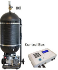 |  |
This technique was firstly used in Sweden around 1977 (, ) as a ‘blower window’ by Ake Blomsterberg, who then continued his research in Princeton University in 1979. This paved a foundation to wider developments and acceptance of blower door test. The initial utilisation was started by researchers who used it to understand building infiltration. With the assistance of blower door, researchers discovered that hidden leak accounted for a significant amount of air leakage, which was seen as a great leap forward in understanding how buildings operate. Blower door was also seen as a useful tool for weatherization and retrofitting work. Since then it has attracted wide attention and generated high demand in building industry. Companies started to form and manufacture blower door units. In 1986, 13 blower door manufacturers were identified by Home Energy in United States, but with only three manufacturers still in the business today: Retrotec, Minneapolis and Infiltec. The blower door technology has gone through significant developments from early bulky, heavy and clunk version, which was made of materials like plywood and Formica to the latest lighter and more compact version made of adjustable metal frame and lightweight fabric door panel with advanced instrumentation. The test duration has also been reduced significantly.
A large number of scientific research related to the blower door technology has been carried out, covering unregulated or temperate/hot climate countries (Ji 2017, Ji 2017, Salehi 2017), modelling/infiltration (, ), building characterization (, , , ), retrofitting (), measurement uncertainty (), indoor air quality () and other relevant aspects (, ). However, the technology comes with its own shortcomings, which include change of building envelope, unrealistically high testing pressure, coarse interpretation of wind effect and demand for skilful training. That was one of the early motivations for finding alternative methods for measuring building airtightness, such as AC method (, , ), decay method (, , ), Pulse method (, , , , , , ) and acoustic method (, , , , , , ).
3. Princple and Historical Development
The pulse technique measures the building airtightness at low pressures by releasing a known volume of air into the test building over 1.5 seconds from an air tank to create an instant pressure rise within the test building and reach a ‘quasi-steady’ flow. Pressure variations in the building and tank are monitored and used for establishing a correlation between leakage and pressure. The method used for the adjustment, which accounts for changes in background pressure, is achieved by deducting background pressure from the raw data. This is described in a previous paper (). A typical pulse test measurement is shown in Figure 3. The readings of building pressure consist of three key stages, pressure variation during quasi-steady period and background pressures before and after the pulse.
A typical pulse test by a unit with 60 l tank (tank pressure measured in bar, building pressure in Pa).
The pulse technique measures the building leakage at various pressure levels similar to leakage measurements using a blower door test process. However, it measures in a dynamic manner instead of taking each individual reading at a steady pressure level. The advantage of this technique is that the test can be done in 11–15 seconds. The challenge lies in the occurrence of the inertia effect of air that flows through openings, which then adds uncertainty to the measurement (). This type of flow is addressed herein as unsteady flow. The percentage of unsteady flow in the quasi-steady period, isolated and evaluated using a momentum equation, is used to account for that inertia effect. The momentum equation is described by eq.(1).

The first two terms of the right hand side of eq.(1) correspond to the momentum change and surface friction. The third term accounts for the inertia effect of the air that flows through the opening.
Table 1 lists a summary of the pulse unit at each developmental stage with a schematic diagram or a photo of each version. As can be seen the initial process involved the delivery of a Pulse of air through the use of a moving piston inside of a large cylinder. This method was superseded by the use of a nozzle attached directly to an air compressor tank. This enabled the removal of the large piston, but the nozzle method necessitates the need to measure the tank pressure throughout the test to determine a volumetric flow rate from the tank. The validity of this process has been shown to be accurate and repeatable as introduced in section 5.1 and further details are reported by Cooper (). More technical details of each iteration are listed in Table 2.
Table 2
System composition of the pulse unit at various developmental stages.
| Stage | 1 | 2 | 3 | 4 | 5 |
|---|---|---|---|---|---|
| Version | Gravity driven piston unit | Compressed air driven piston unit | Nozzle unit | ||
| Tank | N/A | Steel | Steel | Composite | Aluminum |
| Compressor | N/A | Oil based semi-industrial. 99 dB | Oil based semi-industrial. 99 dB | Oil free double piston 65 dB | Oil free double piston 65 dB |
| Solenoid valve | N/A | ¾” 230 VAC | ¾” 230 VAC | ¾” 24 VDC | ¾” 24 VDC |
| Tank pressure transducer | N/A | PMP 1400 (GE) | PMP 1400 (GE) | PMP 5013 (GE) | PMP 5013 (GE) |
| Building pressure transducer | N/A | 200 Hz Furness control (FCO44) | 200 Hz Furness control (FCO44) | 20 Hz Furness control (FCO332) | 20 Hz Furness control (FCO332) |
| Power supply | N/A | Standalone AC/DC converters | Standalone AC/DC converters | Embedded in a control box | Embedded in a control box |
| Pressure reference | N/A | External | External | Internal | Internal |
| Data collection | N/A | A/D converter and BNC box and computer | A/D converter and BNC box and computer | Self-contained RAM | Self-contained RAM |
| Data analysis | N/A | Computer-based Matlab program | Self-contained firmware | Self-contained firmware | |
The work reported in this paper focuses upon experimental investigations utilising pulse units developed at stage 2–5 i.e. no discussion in relation to gravity driven piston unit.
4. Methodology
4.1. Case study buildings
All the buildings that were tested in these experimental studies are shown in Figures 4 and 5. The ones in Figure 4 are dwellings except No.10, which has a size similar with dwellings. All are listed in the format of House Number-House type. The key parameters of the test houses are listed in Table 3.
Test houses (D: detached; SD: semi-detached; ET: end-terraced; MT: mid-terrace).
Buildings used for large building tests.
Table 3
Key parameters of the test houses.
| House Number | Volume (m3) | Age (years) | Position | Construction type | ACH (h–1)50 | Tank (l) |
|---|---|---|---|---|---|---|
| 1 | 157 | >100 | End-terrace | Solid wall | 12.1 | 40 |
| 2 | 196 | >100 | Mid-terrace | Solid wall | 10.5 | 50 |
| 3 | 196 | 10–100 | Semi-detached | Cavity wall | 9.0 | 50 |
| 4 | 213 | 10–100 | Semi-detached | Cavity wall | 6.6 | 50 |
| 5 | 203 | 10–100 | Semi-detached | Cavity wall | 6.8 | 50 |
| 6 | 230 | 10–100 | Detached | Cavity wall | 8.5 | 50 |
| 7 | 447 | 10–100 | Detached | Cavity wall | 8.2 | 50 |
| 8 | 343 | <10 | Detached | Modern SIP | 4.9 | 50 |
| 9 | 157 | 10–100 | Semi-detached | Solid wall | 9.0 | 50 |
| 10 | 371 | >100 | Semi-detached | Solid wall | 7.6 | 50 |
| 11 | 194 | 10–100 | Semi-detached | Cavity wall | 8.3 | 50 |
Three non-residential buildings, as shown in Figure 5, were used for testing to explore the feasibility of measuring the airtightness of large buildings using the Pulse technique.
Prior to testing, all the buildings were prepared according to the UK’s Air Tightness Testing and Measurement Association’s Technical Standard L1 (ATTMA TSL1) for measuring air permeability of building envelopes in dwellings (ATTMA, 2010). The blower-door tests followed the guidelines set out in ATTMA TSL1 and the BS EN:13829 (BSI, 2001), which has been superseded by BS EN ISO 9972. As such, the results should be comparable with those carried out for demonstrating compliance with the UK Building Regulations.
4.2. Experimental setup and test arrangement
Various versions of Pulse prototypes were used in the experimental studies, and the schematic diagrams of compressed air driven piston unit (stage 2) and nozzle unit (stage 3, 4 and 5) are illustrated in Figures 6 and 7, respectively. For the former, the electronic controller operates the solenoid valve by allowing it to be open for 1.5 seconds. The released air is injected to the cylinder to push the piston to the other side with a certain displacement. In this process, the instantaneous position of the piston, the internal and external pressure difference are recorded by CET (cable extension transducer) and pressure differential transducer respectively, and sent to the BNC terminal box via A/D converter card, which allows high sampling rate. Records of data are taken at a frequency of 200 Hz.
Schematic diagram of pulse technique using piston unit.
Schematic diagram and photo of the nozzle unit.
For the latter, the schematic diagram is shown in Figure 7. The compressed air is released into the test building directly through a silencer mounted on the valve (V1) for 1.5 seconds. The silencer helps dispense the air more evenly with a reduced noise level. The subsequent pressure changes in the air tank and test building are respectively recorded by a pressure transducer and a differential pressure transducer (ΔP transducer) and sent to ATT control box for data analysis and storage. This setup does not penetrate the building envelope by using an internal pressure reference tank and indoor setup. The valve (V2) on the internal pressure reference tank is normally open to have an equalised pressure with the ambient environment and it closes when the test starts to provide a useable pressure reference for the ΔP transducer to measure the building pressure response.
The experimental setups of all the studies are summarised in Table 4 to provide details on the prototypes used for testing and the test buildings. The objective of each study is also given. Due to the fact the current version of Pulse unit is designed to test domestic buildings, most of the studies herein were carried out in dwellings or small non-residential buildings to validate each development, assess the repeatability and compare with the steady state method. Studies were also undertaken in a three large buildings with larger volumes to explore the feasibility of testing large buildings.
Table 4
Summary of the experimental setups.
| Study (Section ID) | 5.1 | 5.2 | 5.3 | 5.4 |
|---|---|---|---|---|
| Unit | Stage 2 and stage 3 | Stage 3 | Stage 4 | Stage 5 |
| Test building | The meeting room in the green rectangle in Figure 5c | Building 1: same with 5.1. Building 2: Figure 4 (No. 8). | Same with building 2 in 5.2. | Same with building 2 in 5.2. |
| Objective | Validation and repeatability | Repeatability | Repeatability | Repeatability |
| Study (Section ID) | 6.1 | 6.2 | 7 | 8 |
| Unit | Stage 3 and 4 | Stage 4 | Stage 3 and 4 | Stage 2 and 3 |
| Test building | All the houses listed in Figure 4. | Same with building 2 in 5.2. | Same with building 2 in 5.2. | Buildings shown in Figure 5. |
| Objective | Comparison with the steady state method | Comparison with the steady state method | Environmental impact on the Pulse test | Testing Large building; |
Studies from 5. 1 to 5. 4 were carried out to assess the repeatability of the prototype at each developmental stage. In each repeatability study, the prototype was subjected to repeated tests in a test space with a volume that is close to a typical dwelling. In 5. 1, a comparison was also made to the stage 2 piston unit and stage 3 nozzle unit to validate the feasibility of simplifying the delivery of building pressure change from piston movement to the release of compressed air through a nozzle. In the studies 6. 1 and 6. 2, the stage 3 and 4 nozzle units were compared with Minneapolis blower door model 4 in a range of UK dwellings to see how the measurements, given by both methods at different pressure levels, correlate with each other. In the study 7, the impact of environmental conditions on the Pulse test had been investigated by monitoring the airtightness of a three-bedroom house that was subjected to various weather conditions over a year time. In the study 8, multiple Pulse units (stage 2 and 3) were tethered together to measure the airtightness of three buildings in different sizes, ranging from 632 m3 to 8000 m3.
5. Repeatability
During the course of research and development of the pulse technique, various changes in the system components and operations have occurred, such as the replacement of piston with nozzle, utilisations of differential pressure transducer with lower sampling rate, replacement of external pressure reference with internal pressure reference, utilisation of automated testing process, data collection and analysis. Considering repeatability is one of the key indicators of system reliability, it is important to maintain a good and consistent level of it throughout all the developments. Hence, experimental tests have been carried out at each stage to validate each change. Most of the tests were undertaken under calm or light wind conditions.
5.1. Comparisons with the piston technique
From the piston unit (stage 2) to the nozzle unit (stage 3), there is a significant change in the way of introducing the pressure pulse into the test space, i.e. replacing the compressed air driven piston displacement with direct ejection of compressed air into the building via a nozzle. In the piston unit, the flow rate of released air is quantified by the real time movement of piston, while in the nozzle unit, it is done by monitoring the transient pressure change in the air tank. The consequent change in the mathematical model for determining the airflow rate from the tank, compared to the hardware or software modification based on the same principle, is more significant and hence more likely affects the system performance. Therefore, this section is allocated particularly to the investigation of the validity of this change by subjecting these two iterations to the same testing condition.
Tests were done in a meeting room (Figure 5c) and a comparison of pressure-leakage curves is shown in Figure 8. Good agreement appears and indicates that the nozzle unit is reliable for determining building leakage at low pressures. However, from Figure 8, it can be seen that the piston tests always give slightly lower values of leakage under the same pressure differences. During the piston test, there is an unavoidable leak of air from the narrow gap between the piston and cylinder wall. Therefore, the piston test may underestimate the air leakage rate slightly because it is obtained indirectly from the velocity of the piston.
Comparison of nozzle and piston results.
In addition to the single nozzle and single piston tests, further experimentation was also performed using simultaneous firing of two-nozzles or two-pistons, i.e. two nozzle devices or two piston devices operated at the same time to generate a combined pressure pulse, were used for the measurement. Figure 9 shows the leakage characteristics of the same building obtained by the single nozzle, single-piston, two-nozzles and two-pistons with repeated test runs. A good agreement and repeatability were achieved as indicated by the same trend.
Comparison of the leakage measurement of the building obtained by nozzle and piston units.
It was therefore concluded that the use of the nozzle technique was repeatable and obtained comparable results to that of the piston technique. In terms of function and portability, the nozzle unit also provided a significant advance of the pulse technique.
5.2. Nozzle unit (stage 3)
The stage 2 piston unit and stage 3 nozzle unit are described in details by Cooper (). They have been used to test two buildings based on the University Park campus in Nottingham, as shown in Figures 5c and 4 (No. 8). Building 1 (Figure 5c) is a single cuboid room with a length, width and height of 9.20 m, 6.04 m and 2.45 m, respectively, which gives an internal volume of 136 m3. Building 2 (Figure 4) is a newly built energy efficient house, with three bedrooms on the first floor and one open space for kitchen, dining and living area on the ground floor. The total internal volume of the building is 371 m3. The test results are listed in Table 5, where V4 is the air leakage rate at 4 Pa.
Table 5
V4 of 5 repeated test runs in two test buildings using the nozzle unit.
| Building | Test ID | 1 | 2 | 3 | 4 | 5 | Mean |
|---|---|---|---|---|---|---|---|
| 1 | V4 (m3/s) | 0.17535 | 0.17557 | 0.17704 | 0.17525 | 0.17668 | 0.175 |
| RPD (%) | –0.36% | –0.23% | 0.60% | –0.41% | 0.40% | 98 | |
| 2 | V4 (m3/s) | 0.13744 | 0.13762 | 0.13962 | 0.13858 | 0.13853 | 0.138 |
| RPD (%) | –0.66% | –0.53% | 0.91% | 0.16% | 0.16% | 36 | |
Note: Mean and RPD stand for ‘mean average’ and ‘relative percentage difference from mean’ respectively.
The system composition of piston unit and nozzle unit is almost the same except the different way of introducing the pressure pulse into the test building. The former does it by moving a piston driven by compressed air and the latter does it by releasing compressed air directly into the test house through a nozzle. As reported in 5. 1, the comparison between piston unit and nozzle unit have shown similar repeatability.
5.3. Nozzle unit (stage 4)
The Pulse technique evolved from a lab-based setup to a packaged unit with integrated electronics within a control box. In comparison to stage 2 and 3, the nozzle unit at stage 4 differs itself by:
- using a differential pressure transducer with 20 Hz sampling rate instead of 200 Hz;
- integrating the power supplies, BNC box, differential pressure transducer, A/D converter, data storage and analysis onto a PCB board in a single control box.
Table 1 shows how the laboratory-based equipment was refined to a self-contained control box. Table 6 shows the results of 18 identical consecutive tests conducted in the house No. 8 (Figure 4) using a 40-litre stage 4 nozzle unit performed over a single day. The outside condition at the time of testing was categorised as light wind (0.45–1.34 m/s). The pressure-leakage relationship is represented in the table by a standardised leakage rate at 4 Pa, or V4 (m3/s). The value is derived from a curve fit to data taken directly at the low pressures. The repeatability is good, with most of the tests falling comfortably within ±5% of the mean V4. More details are reported by Cooper and Zheng ().
Table 6
V4 of 18 repeated test runs in a test house.
| Test ID | 1 | 2 | 3 | 4 | 5 | 6 | 7 | 8 | 9 | Mean |
|---|---|---|---|---|---|---|---|---|---|---|
| V4 (m3/s) | 0.117 | 0.119 | 0.122 | 0.120 | 0.118 | 0.118 | 0.124 | 0.124 | 0.115 | |
| RPD (%) | –2.94 | –1.01 | 1.47 | –0.16 | –1.55 | –1.60 | 3.37 | 3.34 | –4.39 | |
| Test ID | 10 | 11 | 12 | 13 | 14 | 15 | 16 | 17 | 18 | 0.120 |
| V4 (m3/s) | 0.123 | 0.121 | 0.123 | 0.119 | 0.116 | 0.116 | 0.125 | 0.119 | 0.123 | |
| RPD (%) | 2.59 | 0.48 | 2.47 | –0.62 | –3.44 | –3.68 | 4.21 | –0.62 | 2.18 | |
Note: Mean and RPD stand for ‘mean average’ and ‘relative percentage difference from mean’ respectively.
In comparison to stage 2 and 3 pulse units, the repeatability of stage 4 pulse unit has decreased, which are a consequence of the two major changes i.e. the use of a differential pressure transducer with lower sampling rate (due to the consideration of cost) and the use of low grade power supply due to the need for system integration. The new power supply on the PCB board produces more electrical noise in the readings than the previous one. However, the repeatability is still within ±5%, at an acceptable level.
5.4. Nozzle unit (stage 5)
During the experimental investigation using the stage 4 pulse unit, a number of practical concerns were noted. They include:
- The overall weight is around 40 kg relying on two people lifting between different levels.
- Condensation formed and accumulated at the port where the tank pressure transducer is installed.
- Some pressure tube is exposed and prone to be affected by external forces such as reflected airflow or manual operation.
- The unit does not have a casing that could protect it during transportation and onsite operation.
Accounting for the issues described above, some re-configurations were made in the stage 5 pulse unit to
- Split the pulse unit into two main parts, with the air tank being separated from the compressor module, both of which are within a single person-handling limit, 25 kg.
- Relocate the pressure transducer to the top of the tank.
- Replace the composite tank used in the stage 4 pulse unit with a 60-litre aluminium tank.
In the following tests, a 60-litre stage 5 nozzle unit alongside a 80 litre stage 4 nozzle unit were used in a three bedroom detached house. The results are listed in Table 7 showing the 60-litre stage 5 pulse unit has maintained a similar level of repeatability with the stage 4 pulse unit. The mean value of air permeability at 4 Pa measured by both units is in close agreement, with a 3.1% percentage difference.
Table 7
Five repeated test runs in the test buildings using two different pulse units.
| Pulse unit | Test ID | 1 | 2 | 3 | 4 | 5 | Mean |
|---|---|---|---|---|---|---|---|
| Stage 4 | V4 (m3/s) | 0.1076 | 0.1048 | 0.1109 | 0.1077 | 0.1067 | 1.3351 |
| RPD (%) | 0.07% | –2.57% | 3.12% | 0.17% | –0.79% | ||
| Stage 5 | V4 (m3/s) | 0.1049 | 0.1126 | 0.1106 | 0.1153 | 0.1110 | 1.3763 |
| RPD (%) | –5.38% | 1.56% | –0.25% | 3.97% | 0.10% | ||
| RPD (%) | 3.1% | ||||||
Note: Mean and RPD stand for mean average and relative percentage difference from mean respectively.
6. Comparison with the Steady State Method
Although the pulse test is designed to take measurements of building air leakage at low pressures, it is frequently asked how the results obtained in the pulse test compare with that of the steady pressurisation test at 50 Pa, i.e. blower door test herein. The flow regimes at low pressure and high pressure levels are hydraulically dissimilar and therefore significant errors will occur in the prediction of air leakage rate from one level to the other in natural conditions, as reported by Cooper and Zheng in a field trial study (). Hence, it is considered not possible to achieve a clear-cut comparison at 50 Pa between the two methods especially under natural conditions where the wind and buoyancy effects are difficult to eliminate. However, direct comparison at 4 Pa is possible to achieve in a sheltered environment where the wind and buoyancy effects are reduced and blower door is able to obtain accurate readings at low pressures. Initial findings showed that both methods provide measurements of Q4 that are in close agreement under sheltered conditions. This was reported by Zheng and Cooper in 2017 (Zheng 2017). Hence, this section focuses on the experimental study in real houses.
6.1. Tests in a range of UK homes
In countries where the well-established airtightness standard sets the building air leakage at 50 Pa as a norm test, it might be difficult for the pulse technique to find its use in compliance test under current standard due to the reasons discussed above. However, it could be regarded as a useful tool for carrying out pre-compliance test, which makes indications to the contractor, or building quality control team if the dwellings are built to the level that is sufficiently airtight to pass the compliance test. Utilising pulse in this way therefore requires an interpretation of Q4 measured by the pulse test to a value of Q50, which is more familiar to many in the construction industry.
The ratio of Q50 measured by the blower door method to Q4 measured by the pulse technique, Q50/Q4, has been looked into in a series of experimental studies carried out in 16 buildings, mostly residential. The blower door unit used in this study is a model 4 Minneapolis blower door (BD-M4) and the pulse unit is a combination of stage 3 PULSE-50 and stage 4 PULSE-80, both gave tests in close agreement as reported by Cooper and Zheng (). The test buildings consist of 2 newly built homes and 14 existing buildings. Both testing methods were used to test each building under the same conditions on the same day.
Due to the uncertainty in extrapolation between low pressure and high pressure, both methods are not expected to agree perfectly. However, the results showed both followed the same trend (). In Figure 10, the Q50/Q4 ratio of most test houses lies in 4–6. Although the sample size of the test buildings in this study is very small, the average value of Q50/Q4 (5.26), represented by the red line in the figure, interestingly is in close agreement with the ratio (5.30). It is calculated using the average pressure exponent (0.66) in the power law equation obtained by steady state tests to a large sample size of dwellings in a number of countries reported by Orme (). This might be because the type of the test buildings is similar to the ones reported by Orme. Nevertheless, the sample size of the test buildings needs to be increased in order to gain a more comprehensive and confident insights. In the figure, the annotation stands for house type, volume (m3), age (years) and wall type. The abbreviations used in the annotation are explained in Table 8.
Q50/Q4 ratio of 16 test houses.
Table 8
Abbreviation table.
| House or building type | Wall type |
|---|---|
| D: detached | CW: cavity wall |
| SD: semi-detached | SW: solid wall |
| MT: middle terrace | SIP: structural insulated panels |
| ET: end terrace | |
ET, 157, >100, SW’ means it is an over 100 years old end terrace house with solid wall structure and internal volume of 157 m3.
If 5.3 is used as the average Q50/Q4 ratio to interpret the pulse test result in pre-compliance test in countries where air leakage at 50 Pa is used in the standard, the prediction of Q50 to the 16 test buildings showed a deviation between 1% and 25% (Figure 11). Hence, this empirical ratio based calculation offers 56% chance of prediction of Q50 with ±10% accuracy in this case study.
Percentage difference of predictions of Q50 to that measured by BD-M4.
6.2. Testing with a known opening increase
A simple check to see which technique is more accurate at measuring an added known opening under natural conditions is also presented. A short sharp-edged circular orifice with a diameter of 100mm was added into a window of a test house, as shown in Figure 12. Assuming an appropriate discharge coefficient of 0.61 therefore gives an effective leakage area (ELA) of 4.7909 × 10⁻³ m2. Tests were conducted for both techniques, BD-M4 and stage 4 PULSE-80 with and without the added opening. The increase in leakage rate measured by both techniques was then converted to an effective leakage area using eq.(2) and compared to the known opening, as shown in Table 9.
Setup of the known opening in house No. 8.
Table 9
Results of other known opening tests using the blower door and stage 4 unit.
| Test ID | Test 1 | Test 2 | Test 3 | Test 4 | Test 5 | |
|---|---|---|---|---|---|---|
| BD-M4 | V4 | –2.9% | 16.5% | 146.7% | –71.3% | 27.1% |
| PULSE-80 | V4 | 4.77% | –3.47% | 32.1% | 9.7% | 5.1% |
V4 stands for air leakage rate at 4 Pa. For BD, V4 is extrapolated from blower door test. For PULSE-80, it is measured directly.

Where, V is the air leakage rate (m3/s), ρ is the air density (kg/m3), and P is the building pressure (Pa). It can be seen that the measurement made by the pulse unit is relatively closer to the known effective area than the blower door measurement in most tests. However, these tests were conducted in natural conditions where environmental factors were not eliminated; hence, there is a level of uncertainty. Therefore, the tests in this section are only for obtaining preliminary insight into comparison of testing accuracy and no solid conclusion should be drawn from them.
7. Repeatability of Tests under different Environmental Conditions
This section investigates the impact of environmental conditions, including indoor/outdoor air temperature, wind speed and direction, to the building airtightness. A recent study () shows an uncertainty of 6%–12% can be caused by wind speeds of 6–10 m/s combined with other sources of error in a steady state test at 50 Pa. Given the low operating pressure of the pulse unit, the wind condition can be considered the foremost important environmental factor for consideration due to its direct impact on the building pressure.
The investigation was performed by conducting a number of tests on the house No. 8 in Figure 4 over a period from September 2014 to September 2015. This period covered the summer, autumn and winter seasons, which provided test scenarios with various wind conditions and outdoor temperatures ranging from 7°C to 21.5°C. Due to the development of the prototype, three versions of prototypes with tanks in two different sizes were used for these monitoring tests; the full details are listed in Table 10.
Table 10
Results of repeated tests under different environmental conditions using stage 3 PULSE-50 and stage 4 PULSE-80.
| Date | Prototype | To/Tin (°C) | Wind speed (m/s) | Wind direction | Q4(m3/h∙m2) | Sub-RPD (%) | RPD (%) |
|---|---|---|---|---|---|---|---|
| 09-Sep-14 | PULSE-50 | 16/20 | 1.57 | SSE | 1.014 | 0.52 | 2.70 |
| 16-Sep-14 | PULSE-50 | 17/20 | 0.9 | NE | 1.065 | 5.58 | 7.87 |
| 26-Nov-14 | PULSE-50 | 7/21.8 | 0.23 | ENE | 1.002 | –0.67 | 1.49 |
| 12-Jan-15 | PULSE-50 | 12/18 | 5.5 | W | 0.953 | –5.44 | –3.39 |
| Mean Q4 by PULSE-50 | 1.008 | ||||||
| 17-Aug-15 | PULSE-80 | 21.5/23.5 | 0.45 | N | 0.985 | 1.23 | –0.24 |
| 24-Aug-15 | PULSE-80 | 17/28.1 | 1.1 | NNE | 0.926 | –4.79 | –6.17 |
| 08-Sep-15 | PULSE-80 | 17.8/18.1 | 0.23 | ENE | 0.997 | 2.46 | 0.98 |
| 10-Sep-15 | PULSE-80 | 18/20.4 | 0.23 | E | 0.973 | 0.04 | –1.40 |
| 18-Sep-15 | PULSE-80 | 19/23 | 0.6 | NNE | 0.963 | –0.99 | –2.42 |
| 21-Sep-15 | PULSE-80 | 14/18.2 | 3.2 | SSE | 0.993 | 2.05 | 0.57 |
| Mean Q4 by PULSE-80 | 0.973 | ||||||
| Mean Q4 by PULSE-50 and PULSE-80 | 0.987 | ||||||
To and Tin are outdoor and indoor air temperature. Q4 is the air permeability at 4 Pa, m3/h·m2.
MK0, MK1 and MK2 represent different stages of prototype development.
Sub-RPD represents the RPD of Q4 of each test in a sub-group of tests (i.e. tests done by PULSE-50 or PULSE-80) against the mean value of the sub-group. RPD represents the relative percentage difference of Q4 of each test against the mean Q4 of all tests given by PULSE-50 and PULSE-80 combined.
It can be seen from Table 10 that the greatest influence upon the variation in Q4 values appears to be due to wind speed and direction. Across all tests, the Q4 values are within ±8% of the mean of all test runs. It must be noted that this variation, among other factors, might also include the difference that exists in different versions of prototypes.
8. Testing with Multiple Units in A Large Building
The original impetus of developing the pulse technique was to overcome the issues of testing the airtightness of large buildings using the steady pressurisation method, such as:
- Large amount of airflow is required to pressurise the building.
- Difficult to achieve even pressure distribution in the building.
The pulse technique was considered to show a significant advantage by testing at much lower pressure and therefore negates the need for large airflow delivery. The setup of multiple pulse units is also flexible and uniform pressure distribution can be obtained by setting up the units evenly in the building. Testing using multiple stage 2 units (piston) and multiple stage 3 units (nozzle) have been carried out in a number of large buildings in order to verify the technical feasibility.
The first one, as shown in Figure 5a, is a two-storey Environment and Education Centre (EEC) studio on Nottingham University Park campus, tested by four piston and four nozzle units respectively. During the tests, four differential pressure transducers were connected to the external and internal tappings with different locations. The studio, divided into 8 zones with wood boards, has a volume of 2130 m3. Figure 13 gives the layout of the studio and the locations of the units.
Floorplan of EEC Studio and locations of pistons/nozzles and internal pressure tappings (T1-T4).
Eight nozzle tests and five piston tests were carried out. Among them, nozzle tests 1~5 and piston tests 1~5 were operated with the maximum air tank pressure (around 10 bar); while, nozzle tests 6~8 were performed with un-fully charged air tank to give the range of pressure pulse similar to that generated by pistons for comparison. The low-pressure leakages obtained by eight nozzle tests is shown in Figure 14. The repeatability of the experimental results is shown to be good, despite the strong wind at the time of testing.
Leakage characteristic measured by piston and nozzle based pulse units.
The second building is a laboratory on the ground floor of Sustainable Research Building (Figure 5c) on the University Park campus. It has a regular cubic shape with a volume of 631.7 m3. Three-piston and three-nozzle tests were carried out and the leakage characteristics is shown in Figure 15. A good agreement has been achieved between tests using multiple units of both types.
Comparison of results obtained by three nozzle units and three piston units.
Multi-piston tests on the third building- a church (Figure 5b) with a volume of 8000 m3 have been carried out together with research partners in Sweden. To determine the lower pressure leakage characteristic of the church, tests were carried out with 7 piston units for generating pressure pulse and 2 differential pressure transducers for measuring the pressure difference across the building envelope. A number of tests have been carried out with vents sealed and unsealed. A few of them were invalid due to the strong wind condition during testing. However, for the valid tests, a good repeatability has been obtained in two testing scenarios as shown in Figures 16 and 17.
Leakage characteristic and power law fitting when vents were unsealed.
Leakage characteristic and power law fitting when vents were sealed.
9. Conclusions
This paper provides a succinct overview of experimental validations testing throughout some of the key developmental stages of the pulse technique over the last 15 years. The pulse unit has gone through a development evolution from being a heavy and bulky unit to compact and easy to use version. Tests have shown that a good level of repeatability (within ±5%) has been maintained. Although being unable to provide direct comparison with blower door test under natural condition due to uncertainty in extrapolation, it was shown both methods have followed the same trend from dwelling to dwelling in side-by-side testing. Known opening tests under natural condition were carried out but no solid conclusion was drawn due to uncertain environment factors associated with external environment. Testing using early multiple pulse units in large buildings have also been carried out and insight has been gained to the feasibility of testing large buildings. It was found that the pulse technique is able to test large buildings and provide results of good repeatability. However, it was also observed that the resilience of the pulse technique to wind effects was reduced in the large and less airtight buildings.