

Introduction
In the European Union, space heating (SH) and domestic hot water (DHW) account for 79% of energy use in households (192.4 Mtoe) (). As around 84% of domestic heat is generated from fossil fuels, there is an urgent requirement to improve system efficiencies and support greater sustainable energy integration. Such improvements are necessary to align with the 2050 climate obligations for decarbonisation under the Kyoto Protocol () and more recently the UN-led Paris Agreement ().
District heat network (DHN) research suggests that improving efficiencies and supporting sustainable energy technologies can be achieved through lowering building hot water supply and return temperatures () ()(). Moreover, histroically there has been a trend towards lower temperature heat medium within DHN (see Table 1), which has the following benefits:
- Improved heat load distribution as lower temperatures are more readily controlled
- Reduced distribution pipe heat losses of up to 75% when compared with high-temperature district heat networks (HTDH) (, ). A lower temperature differential between heat medium and surrounding soil improves the heat transfer coefficient
- Utilisation of low-temperature heat such as heat pumps, solar thermal collectors, and waste heat
- Reduced system design margin. Building heat demand lies between 30–60°C. Therefore, supply from low-temperature district heating (LTDH) more closely matches demand (), reducing the requirements of temperature-blending valves for DHW and enhanced building comfort levels for SH
- Reduced risk of scalding and high-pressure explosion
- Increased piping infrastructure lifetime due to reduced degradation from thermal stress on pipe
Table 1
Development of district heat networks over time.
| Generation | Period | Heat carrier | Temperature (°C) |
|---|---|---|---|
| 1st Generation (1G) | Mid 1800s–1930s | Steam | >100 |
| 2nd Generation (2G) (“High-temperature”) | 1930s–1970s | High temp. pressurised water | <100 |
| 3rd Generations (3G) (“Medium-temperature”) | 1970s–2010s | High temp. pressurised water | 80/40 |
| 4th Generation (4G) (“Low-temperature”) | 2010s–present | Low-temperature water | 50–55/25 |
| 5th Generation (5G) (“Ultra low-temperature”) | 2015–present | Ultra-low temperature water | <49/<24 |
The aforementioned system benefits allow for increased energy efficiency, reduced greenhouse gas emissions, fuel and infrastructure cost reduction, resource optimisation, material utilisation, ease of control, increased system flexibility and improved user comfort levels.
Currently, DHN are supplied predominantly by large-scale centralised fossil fuel () or bioenergy () heat stations. Additionally, there has been some work on solar thermal heat sourced in DHN (, ). However, in future, a shift towards decentralised heat generation from low-temperature and sustainable heat sources should become a more feasible option. As a result, opportunities for prosumer participation, where homeowners can be both buyers and sellers of heat, will become more prevalent (, ). For the prosumer concept to work, the discordance of low-temperature renewable energy supply and domestic demand must be balanced. One solution is thermal energy storage (, , ) or a combination of thermal and battery storage in multi-vector energy systems (MES).
At the University of Nottingham’s Creative Energy Homes test site, project SCENIC (Smart Energy Networks Integrated in Communities) is investigating how the enablement of renewable energy and the prosumer concept can be developed through the integration of community scale heat and power networks. The first phase of project SCENIC involved the design and installation of a heat network. The first of its kind in the world to combine LTDHN with distributed generation at a community level. SCENIC’s heat network configuration has been designed and installed to facilitate a low-temperature heat medium, the uptake of sustainable energy generators, the integration of heat and power networks, smart controls, community level distributed generation, and prosumer participation. A concise site overview is presented in Table 2.
Table 2
Project overview.
| Detail | |
|---|---|
| Occupants | Domestic 12; Office 35 |
| Aim | To provide low-temperature heat and enable the prosumer concept |
| Heat source | Solar evacuated tube arrays, flat plate solar thermal arrays, solar PV arrays, biomass boiler, gas boilers |
| Adjoining buildings | 7 |
| Length of network | 220 m |
The design process of the network first requires heat loads for each of the connected buildings. The heat loads are modelled and act as the base for the rest of the design decisions. Once modelling and the system operating temperatures are decided – in this case 55/25°C, the pipe layout and component selection is possible. This paper presents the modelling, component sizing, system configuration, and proposed energy flows of this novel system.
Building modelling
To enable the sizing of heat network components, steady state peak heat demand and annual heat consumption Figures are required. Network pipe diameter, pump sizing, heat exchanger sizing, and hence the cost and capacity of the network can be projected based on the highest demand. Annual heat consumption Figures are used for heating plant and buffer tank sizing, as well as defining the heat revenues of the system.
Options for modelling peak heat demand include those set out in CIBSE TM54: Evaluating operational energy performance of buildings at the design stage guidelines. However, in order to more accurately reflect the operation of the building in practice, IES-VE software was utilised in the modelling approach. IES-VE’s advanced dynamic thermal simulation provides a higher level of heat demand modelling accuracy due to the added consideration of room occupancy, location and orientation, build material properties, energy system types and efficiencies, heat gains, and air flow (infiltration, mechanical and natural ventilation).
All seven of the CEH was modelled separately. Input data for the IES-VE simulation was taken from CIBSE and BS standards, manufacturer’s datasheets, or real-world published data on the houses.
Peak heat loads
Steady-state space heating (SH) load
The steady state SH load represents a simplified IES-VE building model where certain assumptions remain constant. For example, the outdoor temperature value is assigned as –3.9°C corresponding to the CIBSE guideline design winter temperature. Solar and casual heat gains are not considered so consequently the results are static (see Table 3).
Table 3
Steady-state heating load for each Creative Energy Home. IESVE model simulation data.
| Building name | Instantaneous DHW heat load (kW) | Instantaneous DHW heat load (kW) × diversity factor (0.3) | Steady-state SH load (kW) | Total design peak heat load (kW) |
|---|---|---|---|---|
| David Wilson House | 34.89 | 10.467 | 9.17 | 19.64 |
| Mark Group House | 34.89 | 10.467 | 8.22 | 18.69 |
| EON House | 34.89 | 10.467 | 6.94 | 17.41 |
| BASF House | 34.89 | 10.467 | 4.12 | 14.59 |
| Tarmac House (No. 12) | 34.89 | 10.467 | 3.50 | 13.97 |
| Tarmac House (No. 10) | 34.89 | 10.467 | 2.80 | 13.27 |
| Saint-Gobain Nottingham H.O.U.S.E | 34.89 | 10.467 | 1.85 | 12.32 |
| Total | 73.27 | 36.6 | 109.89 | |
Instantaneous domestic hot water (DHW) peak heat load
Instantaneous DHW peak demand was calculated separately using the assumptions represented in Table 4. The instantaneous DHW peak demand is assumed to deliver hot water to 2 showers and kitchen use for 4 people in each property. The calculated 34.89 kWp/house peak seen in Table 3 is in line with the 37.5 kWp/house proposed in the Danish Standards included in CIBSE’s Heat networks: Code of Practice.
Table 4
Instantaneous hot water peak demand calculation assumptions.
| Parameter | Value | Reference |
|---|---|---|
| Peak hot water demand (ṁ) | 25 L/person/hour (7am–8am) | CIBSE part G – Table 2.10 |
| Heated water temperature change (ΔT) | 50°C (from 10°C to 60°C) | BS 8558:2015 Appendix B |
| Specific heat capacity of water (Cp) | 4.187 kJ/kg.K | CIBSE part G – equation 2.2 |
| Heat capacity equation | Q = ṁ Cp ΔT | CIBSE part G – equation 2.2 |
| Diversity factor | 0.3 | CIBSE – Heat networks: Code of Practice for the UK – Figure 9 |
Peak instantaneous DHW heat demand is unlikely to occur in all properties at the same time. Therefore, to ensure representative results, a diversity/coincidence factor is applied. The diversity factor is the ratio of the effective peak load used. The Danish Standard DS 439, recommended by CIBSE AM12:2013 and BS 8558/BS EB 806-3, gives the coincidence factor as a function of the number of properties served by the heat network. In this case, a site with 7 properties has a coincidence factor of 0.3.
Heat network configuration
Network configuration is determined by the placement of infrastructure, as well as the network size and heat source location. Fortunately, the Creative Energy Homes test site can accommodate a largely soft-dig trenching system with a simple branched pipe network (see Figure 1). Branched networks allow for consumers to be connected to the main loops individually by a smaller service branch. Benefits of branched networks include flexible design, easy installation, and additional branches can be added to the network loop at later stages.
Aerial view of the Creative Energy Homes test site with heat network trenching layout.
As mentioned, project SCENIC is the first MES (Multi-vector Energy System) DHN with truly distributed energy generation. Consequently, a novel network configuration was required to facilitate prosumer and consumer participation at each property. A double loop system has been installed, where a network loop supplies heat to each property via a consumer HIU (heat interface unit) (see Figure 2), and a generation loop delivers heat generated at each property through a prosumer HIU to a CTS (central thermal store) (see Figure 2).
SCENIC double loop heat network with system components. Generation loop (top) facilitates heat transfer from distributed sources to CTS. Network loop (bottom) facilitates heat supply to houses from CTS.
Network component sizing
Heat networks are designed on peak load in winter, yet year round efficiency needs to be considered. Despite peak load needing to be met, oversizing needs to be balanced against technically practical and economically feasible component selection. For most of the year the system will only operate at part load with peak output is only needed for a few hours.
Initially, network operating temperature needs to be selected. Following this, when sizing a heat network, three components are considered:
- Heat source
- Heat distribution/pipe system
- Heat exchanger/heat interface unit (HIU)
Within this section, we consider the sizing of the aforementioned heat network components using the modelled results. Once component sizes have been identified it is possible to present the overall heat network layout within Section 4. Unlike standard heat network component sizing and design, project SCENIC has to consider the integration of distributed generation on all 7 networked properties.
Operating temperatures
The transition to LTDH is widely understood to be the next step in heat network efficiency. Generally, LTDH has a supply temperatures below 55°C and return temperatures of around 30°C described in numerous papers (, , , , , , ). As a result, Project SCENIC aims to achieve a network supply temperature below 55°C for most of the year and a return temperature of 30°C.
Lund, Werner et al. (), the seminal work on the definition of LTDH (4th Generation) describes how future systems can achieve supply and return of 50°C/20°C for most of the year without compromising comfort levels and hygiene requirements. It is understood that operating temperatures should be kept as low as possible to avoid unnecessary heat losses. Additionally, operating temperatures will also effect:
- Capital and running costs
- Heat losses
- Pump and pipe sizing requirement
- Efficiency of heat pumps
- Volume of thermal store required
- Heat exchanger capacity
The relationship between the aforementioned parameters is discussed more comprehensively alongside relevant system component information in the following sections.
Heat source
The generation technologies have been installed before the installation of the heat network except for an evacuated tube solar thermal array on oldest property (David Wilson House). Table 5 specifies the capacity and location of each distributed generation technology. Energy flows are presented later in the paper.
Table 5
Heat source type and generation.
| Building name | Energy generation technology | Peak installed capacity (kW) |
|---|---|---|
| David Wilson House | Evacuated tube solar thermal collector Gas boiler | 4.42 24 |
| Mark Group House | Evacuated tube solar thermal collector | 4.42 |
| EON House | Gas boiler | 12 |
| BASF House | Flat plate solar thermal collector | 3.2 |
| Tarmac House (No. 12) | Biomass boiler Flat plate solar collector | 15 1 |
| Tarmac House (No. 10) | Flat plate solar collector | 1 |
| Saint-Gobain Nottingham H.O.U.S.E | Evacuated tube solar thermal collector | 1.28 |
| Central thermal store | Immersion heater | 12 |
| Total | 78.32 | |
Thermal store
In order to enable intermittent renewable generation, appropriate generation scheduling, and to satisfy peak loads energy storage is required. The tank is sized to match the peak flow rate of 1.99 l/s (based on formula 3) sustained over 10 minutes (600 seconds). Due to stratification, the required supply temperature is only available in one-quarter of the tank. Therefore the tank will need to accommodate 2400 seconds of flow. Hence, the required volume of the tank is:

where S is tank volume (l), F is diversity factor, and V is heat medium flow rate (l/s). With a heat network peak flow rate of 1.99 l/s, the hot water volume capacity required is 4,776 l.
The CTS selected for project SCENIC was a 10,000l accumulator tank with 100mm of polyurethane insulation with 0.23 W/mk thermal conductivity (Figure 3). The tank is capable of storing energy for days or even weeks with minimum heat losses. The tank can operate with a maximum supply temperature of 95°C, and operating pressure of 3 bar, typically 1.5 bar. The tank was oversized to account for additional energy generation installation in later projects.
SCENIC project central thermal store. 10,000 l GALÚ Classic.
The energy stored in the thermal tank is available as sensible heat in the raised water temperature. The capacity of the central thermal store is:

where E is energy content (kJ), cp is the specific heat of water (kJ/kg°C), ΔT is the temperature difference between the hot water and the surroundings, m is the mass of stored water (kg). The temperature difference between the heat medium and surrounding air is assumed to be uniform. Assuming 50% of the stored hot water is available for usage, then tank can accommodate over 202.67 kWh as sensible heat at 55°C.
Heat distribution
In standard DHN a heat transfer fluid, usually water, is passed through a two-circuit system (flow and return). However, project SCENIC utilised a four-circuit configuration comprised of a network and generation loop (see Figure 2). Within the network loop a flow pipe transports hot water from a CTS to the consumer, a return pipe delivers cooled water back. Within the generation loop, a flow pipe delivers heat from the prosumer’s distributed energy source to a CTS, a return pipe delivers cooled water back.
For accuracy in the heat distribution design of such a system we consider the following key factors:
- Correct heat loads – if incorrect, oversizing of pipes will lead to greater heat losses
- Diversity – again to avoid oversizing (see Section 2.1)
- Limiting installation costs
- Avoiding hard-dig areas such as asphalt roads
- Use of polymer pipes for flexibility resulting in less requirement for joints
- Utilisation of twin pipes
Distribution pipe
The pipe has been selected as the heat distribution infrastructure due to its excellent thermal insulation. The polyurethane (PU) foam insulation and corrugated outer jacket help retain heat and allow for flexibility, in turn reducing heat losses, improving ease of installation, and limiting jointing requirement (see Figure 4).
RAUTHERMEX preinsulated bonded pipe main components. Single pipe (left). Twin (bottom) and single (top) pipe (right), ().
The piping system is made up of a crosslinked polyethylene (PE-Xa) water bearing carrier pipe, pentaneblown PU foam insulation and a PE-LLD outer jacket. Consequently, the product is advantageous as it durable, providing corrosion and chemical resistance, has permanently low heat and pressure loss, and very low roughness.
Pipe diameter
Each pipe section must accommodate the peak heat load of those properties down flow of the network. Moreover, when sizing pipe sections the principle, as small as possible, as big as necessary, should be followed.
Network distribution pipe diameter is inferred from the pipe flow rate and pressure loss. Flow rate can is calculated from the known heating requirement and the temperature difference between flow and return pipes. Flow rate is:
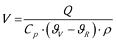
where V is the heat medium flow rate (l/s), Q is the peak heat flow (kW), Cp is the specific heat capacity of water (kJ/kg·K), ϑV is the flow temperature in the network (°C), ϑR is the return temperature in the network (°C), and ρ is the density of water (kg/l).
Using calculated flow rate and the manufactures specification the pipe should be as small as possible without exceeding a 200–250 Pa/m pressure loss, it is possible to identifiy the most appropriate branch pipe sizes.
Pipe configuration
The benefits of using a twin pipe was quantified based on the network operating temperatures and the following heat loss calculation:

where Q is heat loss during operation (W/m), U is thermal heat transfer coefficient (W/mK), ϑB is average operating temperature (55°C), and ϑE is the assumed soil temperature (10°C). Using the equation above the heat loss reduction when using twin compared to single pipes has been calculated (Table 6).
Table 6
Comparison of heat loss in single and twin pipes – project SCENIC.
| Diameter requirement (mm) | 2× single pipes | Twin pipe heat loss (W/m) | Heat loss reduction (%) | ||
|---|---|---|---|---|---|
| Thermal heat transfer coefficient (W/mK) | Heat loss (W/m) | Thermal heat transfer coefficient (W/mK) | Heat loss (W/m) | ||
| 25 | 0.099 | 6.44 | 0.139 | 4.52 | 30 |
| 32 | 0.121 | 7.87 | 0.183 | 5.95 | 24 |
| 40 | 0.151 | 9.82 | 0.211 | 6.86 | 30 |
Pumps
Pumps are fundamental to heat distribution in networked hydronic systems. For DHN, pumps are not the main energy consumer in systems, but correct sizing is important to deliver minimum energy transport costs. Due to variable heat demand maximum duty pumping occurs over very few operating hours. However, pump size must be based on maximum system load, specifically maximum flow and pressure loss as well as peak efficiency. As a result, variable speed pumps with a good control strategy are ideally suited to gain lower heat, less power, and better efficiencies.
Another important factor is temperature difference within a distribution loop as it will affect pumping requirement. If ΔT is low, higher flow rates are required to satisfy heat demand, therefore causing higher pressure loss and hence pumping costs increase. ΔT should be as high as possible to minimise pumping costs.
Pump duty is sized to overcome the flow resistance in the pipework and the pressure differential at HIUs. When determining pump duty the following hydraulic requirements are essential:
- Total inflow Qi (l/s) equals duty flow of pump Qp (l/s)
- Duty head of pump Hp (m) ≥ Total head Htotal (m)()
Alongside these hydraulic requirements, a minimum pump energy consumption must be taken into account. Therefore, both generation and network loops use the pump which has the highest energy efficiency on the market, which is designed for pumping liquid through heating systems with variable flows. The pump duty point can be optimised to reduce energy costs. As a result, pumps were sized to work at 30–75% of the total load. It is important for correct operation that the system range lies within the duty range of the pump (see Table 7).
Table 7
Grundfos – MAGNA3 D 32-120 F Model B duty range compared to project SCENIC parameters ().
| Parameter | MAGNA3 (N) Single-head pumps ranges | Project SCENIC ranges |
|---|---|---|
| Flow rate, Q | 21.81 l/s | 1.99 l/s |
| Head, H | 18 m | 12 m |
| System pressure | 1.6 Moa (16 bar) | Max. 3 bar |
| Liquid temperature | –10 to 110°C | 30°C to 55°C |
Overall, benefits of the pump include low energy consumption, built-in differential pressure and temperature sensor, heat energy monitor, and easy system optimisation.
Heat exchanger
Heat exchangers separate the primary heat network and secondary consumer circuits. The appropriate Heat Interface Unit (HIU) containing flat plate heat exchangers are required based on peak kW SH and DHW requirements (see Table 3), and system operating temperatures.
The domestic properties in project SCENIC have preinstalled heating and hot water systems, as a result, a direct connection was not an option for SH. An indirect HIU was selected for both SH and DHW to provide a physical barrier between primary and secondary loops. In LTDH a heat exchanger barrier between loops prevents the spread of Legionella bacterium. As the temperature in the network buffer tanks is likely to fall below the required 60°C to prevent the spread of Legionella, a DHW heat exchanger is essential. DHW temperatures will be boosted on the secondary side with an immersion heater to meet the 50°C tap temperature requirement.
For the network loop, supplying SH and DHW to each property, a Danfoss FlatStation – 7 Series DS Fully Insulated was chosen (Figure 5). Furthermore, a bespoke Danfoss FlatStation – 3 Series BS Basic Fully Insulated was designed to accommodate prosumer participation within the generation loop (Figure 5). Figure 6 illustrates how the FlatStation redesign facilitated the supply of heat from distributed generation sources within buildings into the network for distribution.
HIU in situ outside the Tarmac CdFH 4 house. Prosumer unit (right), consumer unit (left) ().
Danfoss FlatStation – 3 Series BS Basic Fully Insulated Indirect Prosumer HIU circuit diagram. Key: 1 – differential pressure controller, 2 – on/off valve, 3 – isolation valve, 4 – pump, 5 – thermostatic valve, 6 – energy meter, 7 – electrical wiring box, 8 – heat exchanger, 9 – hot water tank with immersion temperature sensors, 10 – temperature sensor node.
Sizing
Table 8 specifies the selection of HIU on each of the test site properties. Sizing was based on heating capacity and supply/return temperature. Furthermore, Danfoss HIU significantly outperform others on the market due to their specialised valve technology and energy saving features.
Table 8
HIU specification and location – project SCENIC.
| Parameter | Consumer unit | Prosumer unit | |
|---|---|---|---|
| Product | Danfoss FlatStation – 7 Series DS Fully Insulated | Danfoss FlatStation – 7 Series DS Fully Insulated | Danfoss FlatStation – 3 Series BS Basic Fully Insulated |
| Model | VVX-I-FI-1-3 | VVX-I-FI-1-2 | VX-2 |
| Installed on | Mark Group House, David Wilson House | BASF, EON, Nottingham, Tarmac 10, Tarmac 12 | All |
| Heating capacity | SH 10 kW; DHW 35 kW | SH 7 kW; DHW 35 kW | 7 kW |
Energy Flows
Typically heat networks require two energy inputs, heat energy to compensate for distribution heat losses, and electrical energy for pumping to compensate for frictional losses. Within this paper we have discussed the design of project SCENIC’s heat network, however, as a MES both heat and power networks will be linked. As a result, the energy inputs and outputs are more complicated than the typical model. Figure 7 illustrates how the energy flows and system configuration will operate.
Energy flow outline project SCENIC.
The extent to which each energy technology will supply heat or power will depend on the scheduling scenarios to be tested within the next phase of the project.
Conclusions
The paper discusses the design and sizing of the first community scale MES heat and power network with distributed energy generation. Prosumer participation is facilitated through a double loop heat pipe configuration, allowing consumers to be both buyers and sellers of heat. In addition, the use of renewable energy generation and energy storage enables LTDH, which in turn reduces operational costs, heat losses, energy consumption and carbon emissions.
In order to reduce the well-documented system design margin, the SCENIC heat network will operate at low temperature. To permit LTDH, there must be adequate heat transfer through radiators inside each property. As a result, the next phase of project SCENIC will tackle the redesign of interior heating systems to allow heat to be input and output from the properties. The adequate transfer of heat is essential to maintain comfort levels and reduce the energy consumption of the network.
Heat and power network integration will be addressed in the next phase of the project through the installation of a 23 kW lithium ion battery. The battery will power an immersion heater in the CTS and distributed heat generation technologies. In turn, the battery will be charged by the numerous distributed photovoltaic arrays on site.
A formative element in achieving system efficiency is the improved operation and scheduling of the technologies. A holistic control approach for optimising decentralised heat generators, pumps, and valves will require well-functioning monitoring, communication, and decision support tools. As a result, a large part of project SCENIC will be focussed on controlling the system components designed and sized in this paper. A multi-objective, object orientated optimisation approach will be used focussing on real-time data to support decision making through a building energy management system (BEMS).
In summary, infrastructure has been installed at the University of Nottingham’s Creative Energy Homes test site to facilitate distributed generation and the prosumer concept in a combined heat and power network. For the heat network, overall configuration, component sizing, and HIU redesign have been explained in this paper. The work presented here acts as a base from which power integration, control systems, and prosumer business model design can be built upon extending the relevance of the projects outcomes.